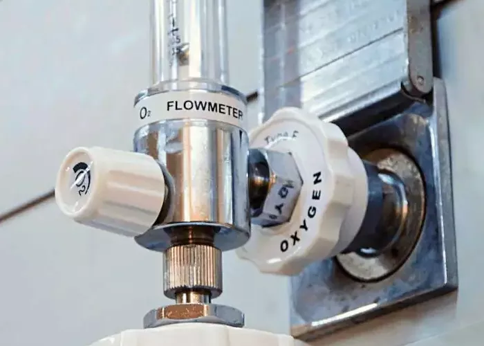
A turbine flow meter is a widely used flow measurement device that operates based on the principle of fluid flow-driven rotation. This device is employed in numerous industries to measure the volume of liquids and gases moving through a pipeline. Its efficiency, accuracy, and ability to handle a broad range of fluid types make it a preferred choice in various applications, including petroleum, chemical processing, water treatment, and aerospace engineering. This article explores the structure, working principle, applications, advantages, and limitations of turbine flow meters.
What Are Turbine Flow Meters
A turbine flow meter consists of a rotor with multiple blades positioned in the path of the flowing fluid. When the fluid passes through the meter, it causes the rotor to spin. The rotational speed of the rotor is proportional to the velocity of the fluid, allowing for an accurate determination of the flow rate. The motion of the rotor is then translated into an electrical signal, which is further processed to obtain precise flow measurements.
Components of a Turbine Flow Meter
Rotor (Turbine Wheel): The main component that spins when fluid flows through the meter.
Flow Straighteners: These help in conditioning the flow and reducing turbulence to ensure accurate readings.
Bearings and Shaft: Provide smooth rotation and minimal friction for the rotor.
Pickoff Sensor (Magnetic or Hall Effect Sensor): Detects the rotor’s movement and converts it into an electrical pulse.
Housing (Meter Body): Encloses all internal components and provides durability and resistance to external conditions.
Signal Processor: Processes the electrical signals and converts them into readable flow data.
Working Principle of a Turbine Flow Meter
The operation of a turbine flow meter is based on the mechanical energy of the fluid. As the fluid enters the meter, it impinges on the rotor blades, causing the rotor to rotate. The rotational speed of the rotor is directly proportional to the velocity of the fluid.
A magnetic or optical sensor detects the rotation of the rotor and generates pulses. These pulses are counted and processed by a transmitter or flow computer to determine the volumetric flow rate. The formula used to calculate the flow rate is:
Q=K×N
Where:
- Q = Flow rate
- K = Meter calibration factor (determined through calibration)
- N = Number of pulses per unit time
By analyzing the frequency of the pulses, the flow meter provides real-time flow data, which can be used for monitoring and control purposes.
Applications of Turbine Flow Meters
Turbine flow meters are utilized in various industrial and commercial applications due to their precision and adaptability. Some common uses include:
Oil and Gas Industry: Measuring the flow of crude oil, refined petroleum products, and natural gas.
Chemical Processing: Monitoring the flow of chemicals in manufacturing plants.
Water Treatment Plants: Measuring the flow of potable and wastewater.
Pharmaceutical Industry: Ensuring accurate fluid measurements in drug manufacturing.
Food and Beverage Industry: Measuring ingredients like milk, syrups, and juices.
Aerospace Applications: Fuel flow monitoring in aircraft systems.
HVAC Systems: Measuring flow rates in heating, ventilation, and air conditioning systems.
Advantages of Turbine Flow Meters
Turbine flow meters offer numerous advantages that make them a preferred choice for flow measurement:
High Accuracy: Provides precise readings with minimal error.
Wide Measurement Range: Capable of handling different flow rates and fluid viscosities.
Low Pressure Drop: Minimal resistance to fluid flow, reducing energy consumption.
Quick Response Time: Ideal for real-time monitoring and control applications.
Cost-Effective: Offers an economical solution for flow measurement compared to other advanced meters.
Durability: Designed with robust materials for long service life.
Ease of Maintenance: Simple structure allows for easy cleaning and part replacement.
Limitations of Turbine Flow Meters
Despite their numerous advantages, turbine flow meters also have some limitations:
Not Suitable for Highly Viscous Fluids: High-viscosity fluids can reduce rotor movement and cause inaccurate readings.
Requires Clean Fluids: Solid particles in the fluid can damage the rotor and bearings.
Limited Use for Low Flow Rates: Accuracy may decrease at very low flow velocities.
Wear and Tear: Bearings and rotor may experience wear over time, affecting accuracy.
Sensitivity to Fluid Properties: Changes in temperature, density, and pressure can influence measurement accuracy.
Selection Criteria for Turbine Flow Meters
When selecting a turbine flow meter for a specific application, several factors must be considered:
Fluid Type: Ensure compatibility with liquid or gas properties.
Flow Rate Range: Select a meter that can handle the expected flow range.
Pipe Size and Connection Type: Match with the existing pipeline specifications.
Accuracy Requirements: Choose a meter with the required accuracy level.
Operating Conditions: Consider temperature, pressure, and environmental factors.
Material Construction: Opt for corrosion-resistant materials for harsh environments.
Maintenance and Calibration
Regular maintenance and calibration of turbine flow meters are essential to maintain accuracy and performance. Key maintenance practices include:
- Periodic cleaning to remove deposits and debris.
- Inspecting bearings and rotor for wear and replacing them as needed.
- Recalibrating the meter according to manufacturer recommendations.
- Checking and adjusting the signal processor for accurate pulse counting.
Conclusion
Turbine flow meters are reliable, accurate, and cost-effective solutions for measuring fluid flow in various industries. Their simple yet effective working principle, combined with their advantages, makes them a popular choice for numerous applications. However, proper selection, maintenance, and calibration are crucial to ensure optimal performance. By understanding how turbine flow meters work and their operational characteristics, industries can make informed decisions to achieve efficient flow measurement and control.

